HOME — TANDEM TRACK
TRACK · PRINTED TANDEMS
PEROVSKITE-SILICON TANDEMS
ERA GROUP × IPCE RAS

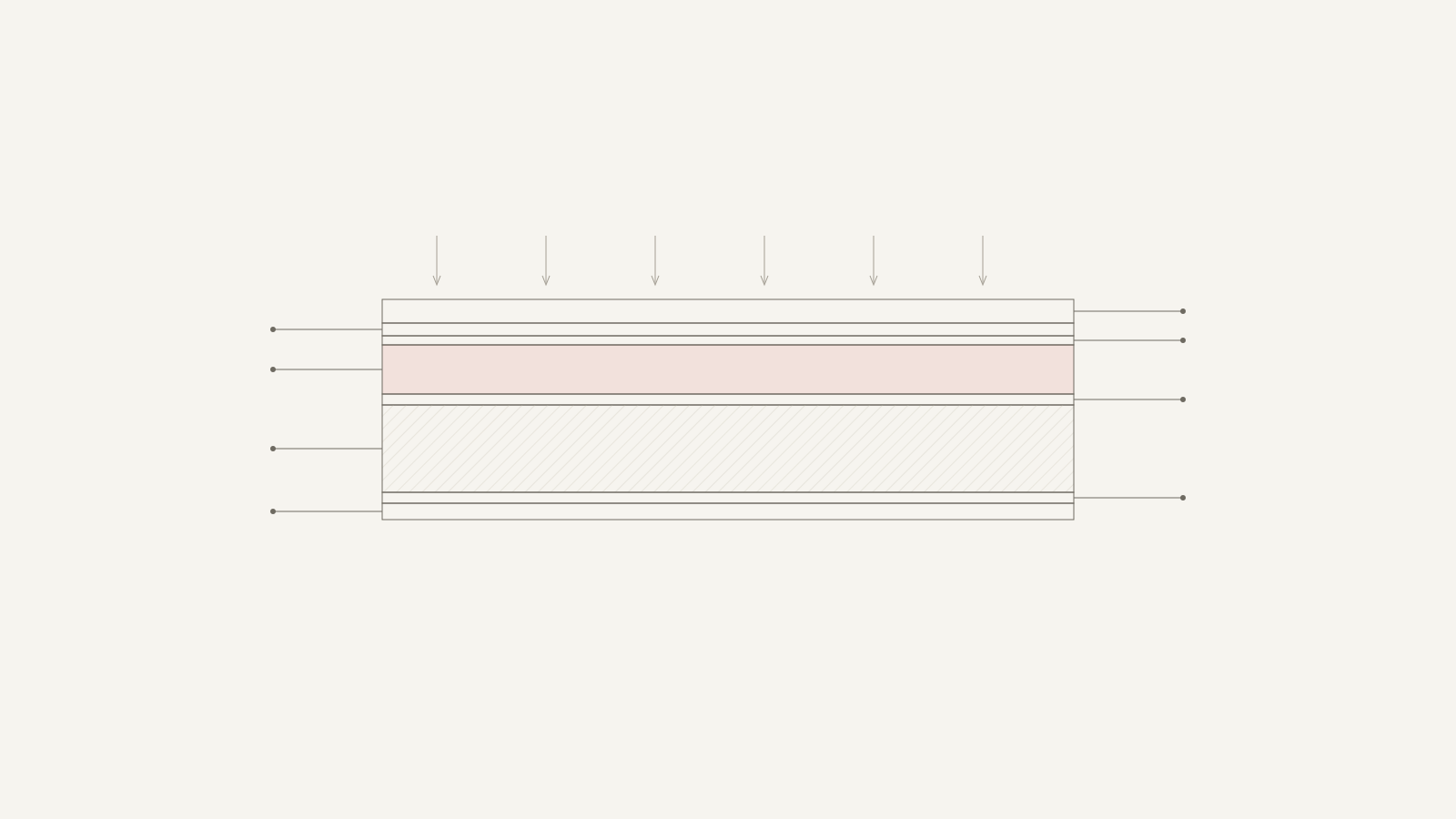
Perovskite-on-silicon tandem — thin-film cell architecture
THE SUBJECT
Technologies for tandem solar cells — perovskite on textured silicon (HJT): a perovskite top cell deposited onto a textured heterojunction silicon bottom cell.
KEY RESEARCH TRACKS
Electrodeposited PEDOT–fullerenol
Solvent-free hole-transport layer with dense morphology — an alternative to SAM on textured HJT. Compatible with slot-die.
Sn/Ge supramolecular buffer
Level alignment and suppression of reactions at the 2T interface between top and bottom cells.
Multi-mechanism T80 forecast
In-situ EIS separates degradation channels instead of single-Ea Arrhenius extrapolation. Maps to ISOS-L2/D3.
PMHS/PDMS encapsulation
Bilayer polymer protection demonstrated at 80% RH humidity stress (Baeva et al., 2023).
T80 METHODOLOGY
IN-SITU EIS
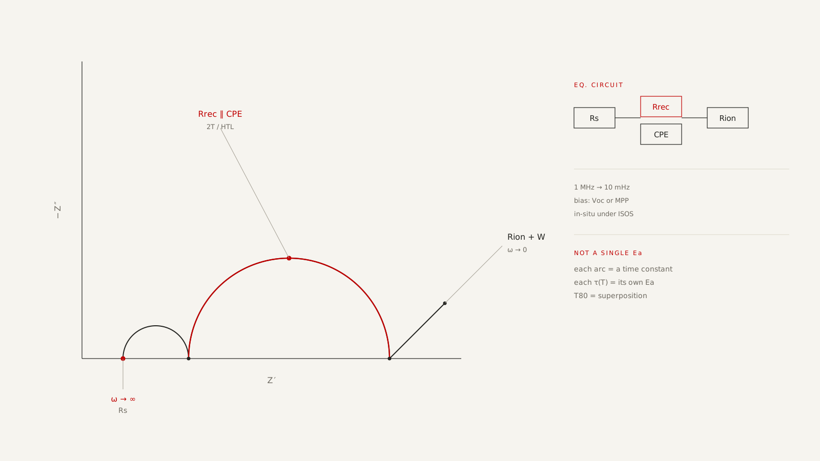
A single-activation-energy T80 is systematically wrong when several processes run in a perovskite at once. In-situ EIS records the impedance spectrum during stress aging and splits degradation into channels, each with its own time constant.
Why Arrhenius fails
The extrapolation T80 = f(exp(−Ea/kT)) assumes one dominant mechanism. In a 2T tandem on textured HJT, ion migration, top-cell interface recombination, contact drift and electrode corrosion run in parallel. A lab “T80 > 20,000 h” from a single Ea is a methodological risk for pilot certification.
Protocol
The device ages under ISOS-L2 (light soak) and ISOS-D3 (damp heat). EIS is taken during the stress, not after.
1 MHz → 10 mHz, Voc or MPP bias. High frequency is Rs, mid is the interface, low is ions.
Rs — Rrec∥CPE — Rion(+W). Each element is a Nyquist arc, each a separate τ.
Element trajectories in time give a superposition of mechanisms. The forecast maps to ISOS and IEC 62941.
Channels visible in the spectrum
Series resistance and electrode corrosion. Rising Rs kills fill factor before the perovskite dies.
Recombination at the top-cell / hole-transport interface. The main yield killer after a MW pilot.
Halide migration and hysteresis. The low-frequency tail (Warburg/Gerischer) grows before PCE drops.
Each channel has its own activation energy. They cannot be collapsed onto one Arrhenius line.
Two ways to say “T80”
ISOS-L2 · ISOS-D3 · IEC 62941
One Ea, accelerated aging, extrapolation. A handsome number that hides which mechanism will kill the module in the field.
Several τ, spectrum under load, a conservative bound for certification. Addresses 2T interface degradation directly.
Track methodology — not a report from an industrial line. Full protocols and raw spectra are shared under NDA.
SCIENTIFIC FOUNDATION — IPCE RAS
The A.N. Frumkin Institute of Physical Chemistry and Electrochemistry (IPCE RAS) — institutional continuity since 1929 (95+ years), the Rehbinder and Deryagin scientific schools. The institute covers the full chain: "synthesis — film — device — characterization".
The Tameev group is the core of the photoelectric materials and devices program, with publications in Nano Energy, Scientific Reports, Applied Physics Letters, J. Mater. Chem. C and others.